 | Antique Tractor Resource Page |
| Home | Gallery | Forums | Ads | Store | ANTIQUETRACTORS.COM |
| Antique Tractor Resource Page |
| Allis Chalmers | Case | Farmall IH | Ford 9N,2N,8N | Ford |
| H. Ferguson | John Deere | Massey | Minn. Moline | Oliver |
The Fordson Improved Vaporizer Early in 1950 an improved manifold was introduced for the Fordson Major. This was announced to the dealer service departments on the 15th May 1950, and was to replace the "N" type vaporizer that was used from 1929 onwards. It was claimed greater fuel efficiency was obtained with this new manifold, leading to lower consumption and less sump dilution. It was also claimed that the machines could achieve better idling characteristics, probably due to the use of the carburetor in place of the original choke unit and separate jet and float assembly. The main advantage after economy as far as the farmer was concerned was that the machine proved quicker to warm up and allowed for a faster turn over to vaporizing oil, which meant that work could be undertaken that much quicker.
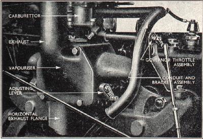
Many restorers of both N and E 27N's have asked me the same question in relation to this manifold...Does this belong to my tractor?.......should I keep it?,...... Does it detract from the originality of the machine?. Well my personal view is...it depends on your own ambitions and perspective when restoring your particular machine. If it fitted on a model "N"...well then in the true sense of full restoration, historically the tractor was made with the early type vaporizer fitted. However in the spirit of working modifications. If it has been adapted to your machine during it's working life, then it is part of it's character. No one but the most pedantic of people would criticize you for leaving it on...remember it's your machine, as individual as you are...it's up to you! The vaporizer itself is easily recognizable by it's appearance. It differs considerably from their early manifold, the most notable point of reference being that the exhaust pipe , rises up from a formed casting on the front and top of the hot plate referred to as the "fire box". The early manifold had the exhaust pipe emanating from the underneath of the manifold held in a cast cup to the bottom left as viewed from the front. Another prominent feature which separates the two is that the early manifold had the float chamber as part of the manifold cover plate, recognizable by the wing shaped adjuster needle on the float chamber assembly. These are not included on the more modern manifold. There a number of reasons why Fordson owners may wish to change over manifolds on their machines, whether it be because the original is beyond repair and the modern manifold is the only one available, or that the old type manifold is getting thin and is set aside to reduce wear. To install the new type manifold adopt the following procedure: 1) Disconnect the controls, governor, choke and ignition. Before fitting the new type manifold the following parts will need attention. Vertical silencer assemblyIf the old manifold utilizes the type of exhaust assembly which sees the exhaust pipe attached directly to the manifold by means of a "U" bend, instead of the cast cup type attachment, Cut off the "U" shaped portion at the base of the exhaust pipe leaving an overall dimension of 34.5" in length in the bottom of the pipe. Alternatively if another length of suitable dimension pipe is available this will allow the original pipe to be retained for converting back. Governor armRemove the ball from inside the governor arm ( where the vertical rod connects) and replace it on the outside of the arm, this is to make sure that the vertical rod, does not catch on the manifold body. Ignition advance and retard rodRemove the support bracket from the front of the rod and replace it with the loop facing upwards, this will allow extra clearance for the rod over the manifold. Fitting the new manifoldExperience has taught me that the carburetor is best fitted to the manifold before fitting to the tractor, it is also important not to forget to fit the plain washer between the manifold and and the spring washer, when fitting the governor throttle shaft assembly. Be sure that the throttle shaft fits accurately on the spade tab, which is part of the the throttle butterfly assembly. It is also important to ensure that the drain valves are fitted in the base of the vaporizer body and the deflector plate is fitted under the front drain valve to stop excess fuel pouring on to the magneto! In order to fit the manifold to the engine the following sequence should be adopted. 1) locate the six ring gaskets around the inlet and exhaust ports. The tractor is now ready to start!! There are a couple of points worthy of note with this new type manifold the first one being the heat control mechanism. New vaporizer heat controlOn the front side of the vaporizer can be seen an arm protruding from the "Fire box".This Arm has four settings and is retained in the chosen position by a lock screw the inner position (nearest to the engine) is the cold position, as the arm is moved away from the engine the shutter is progressively moved to the hot position. Position 1, allows the exhaust gas to escape directly to the manifold and bypass the inlet manifold, use this position for maximum loads in hot weather. Position 2, Most exhaust gas still goes straight to the manifold but a proportion is now diverted to heat the inlet manifold in order to help vaporize the ingoing mixture...use this setting for medium loads. Position 3, More of the exhaust gas is now diverted to the heating chamber or "Fire box"...again medium loads, cold weather. Position 4, This is the notch furthest from the engine it is without doubt the best setting for light running and for tick over. More importantly it is most suitable for rally work. IdlingAt idling speed the air passage through the carburetor is almost completely blocked off by the butterfly valve being firmly pushed against its stop, thus shutting off most of the air to the engine. The fuel at this stage being metered by the idling adjustment screw and then entering the induction passage through a small orifice near the butterfly. The engine must be at working temperature Idling adjustmentThe engine must be at working temperature, and in the case of T.V.O engine running on T.V.O. make sure the choke control is fully open and the throttle is closed, screw the stop screw until the engine is running fast, make sure the idling mixture screw is free and open about 1. 1/2 turns. Now set the throttle stop screw by turning anti clockwise until the engine slows down. Before the engine stalls adjust the mixture screw until the fastest engine speed is obtained, if this is to fast slow it down by another adjustment of the the throttle stop screw. Anti-clockwise is for slower and clockwise for faster. Carburetors for one reason or another on old machinery can be very temperamental, it maybe that the float in the chamber has worn and that the shut off point is incorrect. This will lead to the tractor smoking and running "lumpy" when on full throttle on the other hand if it shuts off to early it will create weak spots in the fuel supply...time and patience is the only answer, trial and error. One last point worthy of note, is that alot of symptoms connected to bad or poor running are unnecessarily blamed on blocked jets, when in fact they are air leaks from gaskets. With any fuel container near heat it is imperative that there are no leaks, so check the gaskets and the felt washer which is held by the gland nut. This is designed to stop fuel leaking along the adjustable main jet. If it is worn, replace it! it is not only safer, but it will stop that annoying steady drip...drip! I hope that this information has been of some help......All that remains is to wish you all, safe and happy mendings from the UK.
| ||||||||